I. Application Background
(1) On-site Background
In petrochemical production facilities, moving equipment such as pumps, compressors, fans, motors, and gearboxes, as well as static equipment such as pipelines,
supports, and connectors, are constantly operating under high load and continuous conditions. Due to factors such as vibration, temperature, and medium corrosion,
the equipment is prone to early problems such as bearing wear, imbalance, misalignment, loose bolts, and structural resonance. If not detected in time,
it may lead to unplanned shutdowns or safety accidents.
(2) Customer Core Requirements
① Conduct condition detection on in-service equipment without stopping the operation;
② Detect early abnormalities of the equipment in advance and achieve predictive maintenance;
③ Reduce the frequency of manual inspections and reliance on subjective experience;
③ Applicable to high-noise and high-risk working environments.
II. Detection Difficulties
① Background noise in the plant area is high (pumps, compressors, and fans operating simultaneously);
② Traditional point-type vibration detection has limited coverage and is difficult to comprehensively perceive;
③ Some equipment is located at high positions and in narrow spaces, making manual detection risky;
④ Early fault signals are weak and easily masked by environmental noise.
III. Solution and Detection Methods
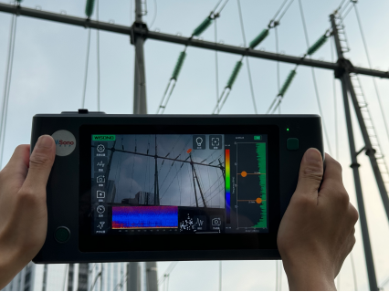
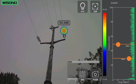
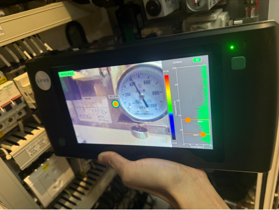
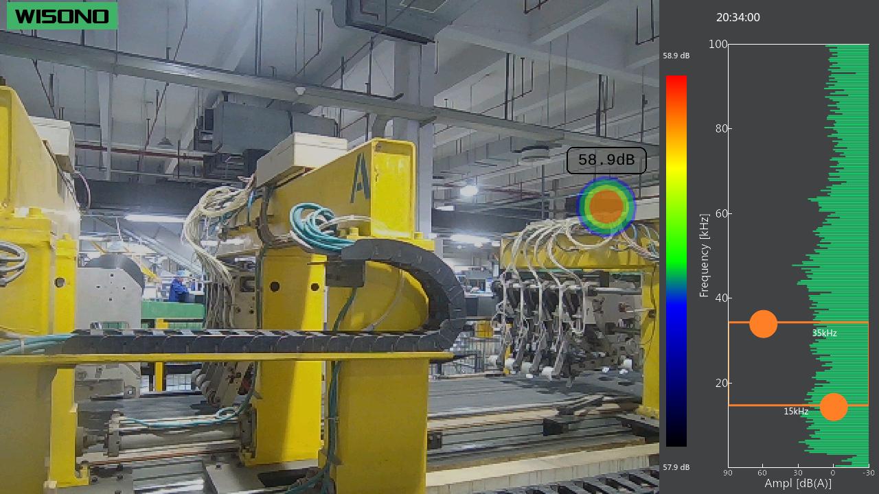
The sound vibration detector developed by Wisono Technology Co., Ltd. (model: NV-D800) is used.
Through high-sensitivity acoustic and vibration sensors, it collects the sound vibration signals transmitted by the equipment structure.
Combined with spectral analysis, time-frequency analysis, order analysis, and AI voice recognition algorithms,
it makes a comprehensive judgment on the equipment's operating status.
Technical Features:
① Non-contact/Low-contact detection, with high safety;
② Multi-channel synchronous collection, covering key parts;
③ Strong anti-noise ability, suitable for complex industrial environments;
④ Supports long-term online monitoring and trend analysis.
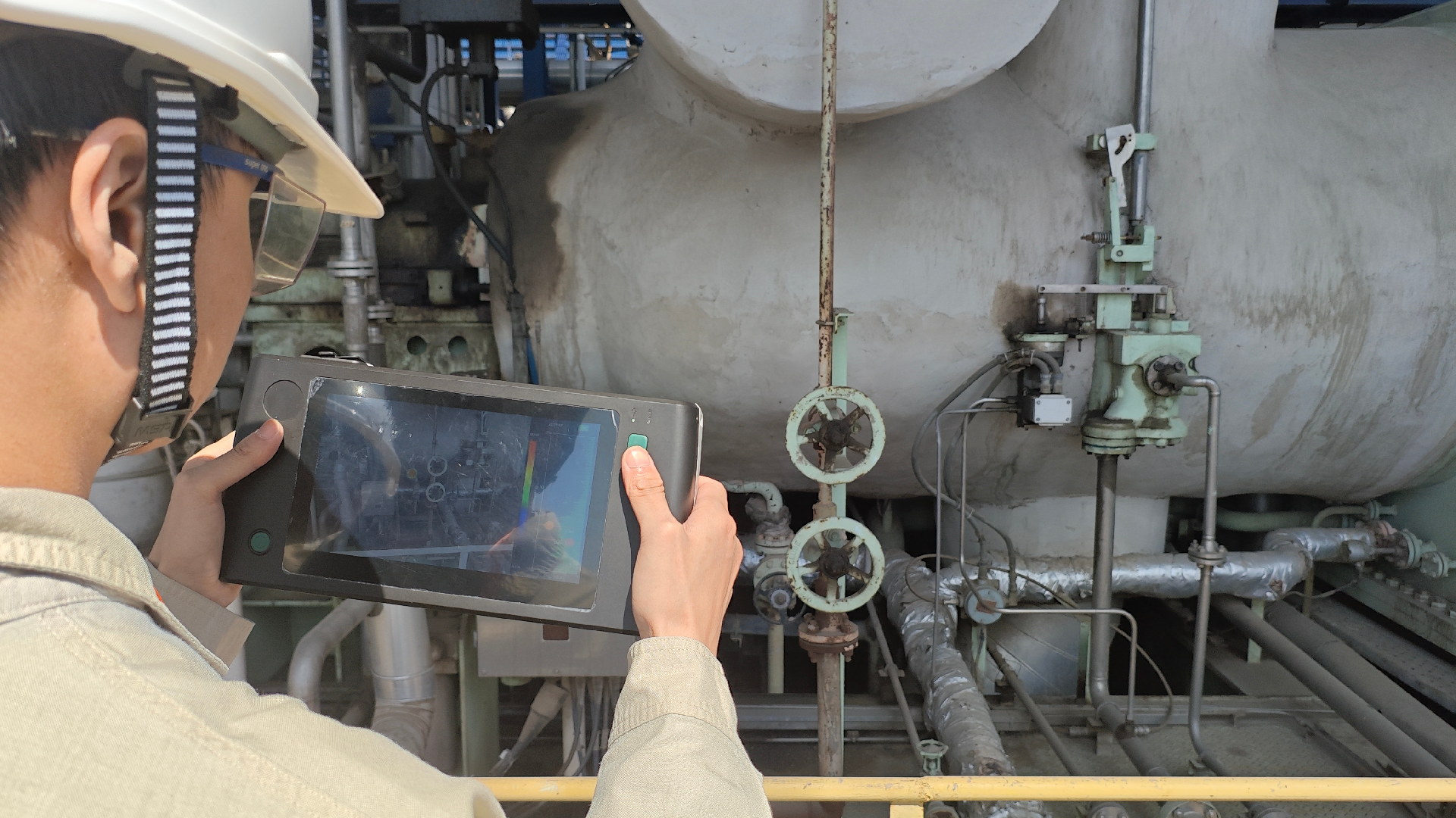
IV. Explanation of On-site Detection Process
① Install sound vibration sensors at key parts of the equipment (bearing seats, casing, support structures);
② Connect the sound vibration detector to establish a real-time collection channel;
③ Collect baseline data under normal operating conditions of the equipment;
④ Conduct frequency domain and time-frequency domain analysis of the operating data;
⑤ Compare abnormal characteristic frequencies and energy changes to identify potential fault types.
V. Detection Results and Effect Display
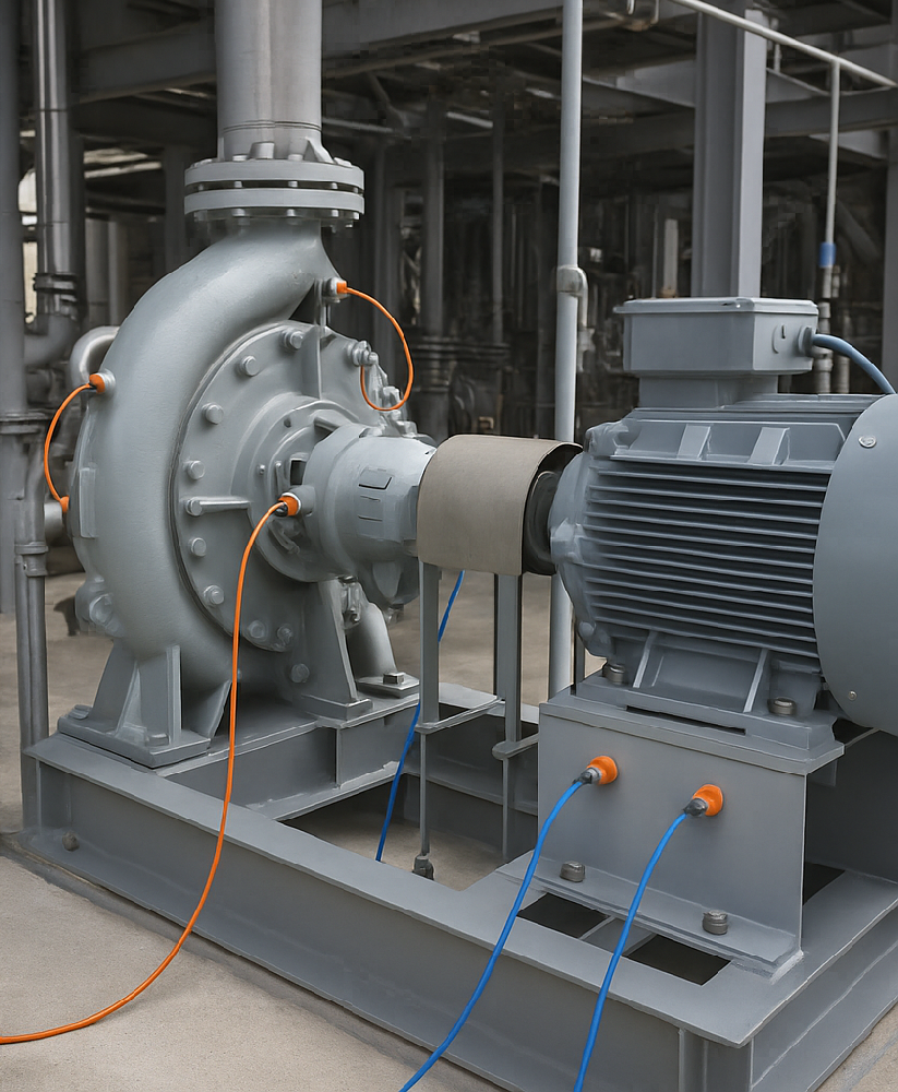
Figure 1 Circulating hydrogen compressor
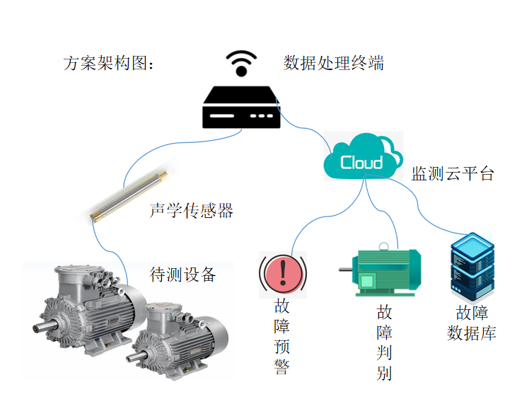
Figure 2 Scheme Architecture Diagram
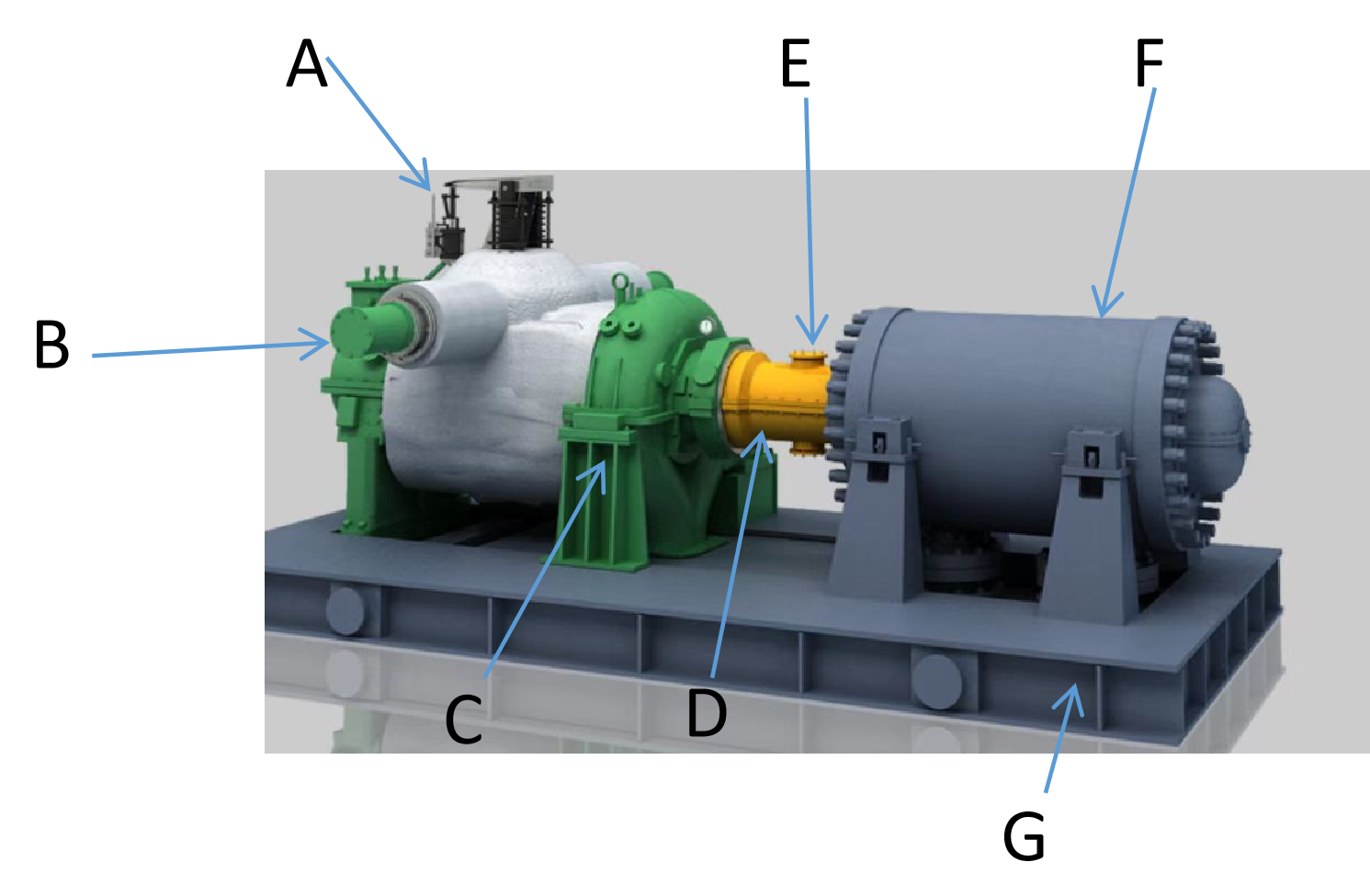
Figure 3 Monitoring Scenarios
(A) Inlet Port: Captures the low-frequency rumbling sound caused by blade stall, detecting the precursors of surge 5-10 minutes earlier than vibration monitoring;
Instantaneous high-frequency pulses from the impact of metal/hard objects on the impeller; Identifies abnormal valve opening or filter blockage-induced airflow vortex noise.
(B) Inlet End Bearing Housing: Wear of the thrust bearing causes rotor wobbling, generating axially friction hissing sound;
Semi-frequency harmonic noise appears before vibration signals; Ultrasonic emission signals of bearing race defects in the ultra-high frequency range.
(C) Compressor Shell: Amplitude fluctuations of frequencies caused by blade fractures or corrosion pits;
Broadband turbulent whistling from high-pressure hydrogen leakage; Structural noise caused by insufficient shell stiffness.
(D) Outlet End Bearing Housing: Failure of radial bearings, higher load at the outlet end, fault noise energy concentrated in 1-3 kHz;
Bubble rupture sound generated by lubricating oil foaming; Point erosion of the bearing surface caused by electrochemical corrosion, with random peaks in the sound pattern;
(E) Coupling: Periodic "clicking" sounds caused by angular error of the diaphragm coupling; High-frequency metal knocking sounds;
Continuous friction hissing caused by dry lubricating grease;
(F) Motor: Side-frequency noise generated by rotor breakage; High-frequency current noise caused by frequency variation driven by bearing electrochemical corrosion;
Imbalance of the cooling fan.
(G)Base: Loose anchor bolts; Structural noise caused by thermal deformation of the inlet and outlet pipelines.
| Monitoring System Configuration for Recirculated Hydrogen Compressor | ||
| Serial Number | Content | Quantity |
| 1 | Unidirectional accelerometer | 6 |
| 2 | Three-axis accelerometer | 2 |
| 3 | Sensor cable (1.5m) | 6 |
| 4 | Sensor cable (1.5m) | 2 |
| 5 | Pre-amplification and filtering module | 1 |
| 6 | Signal Acquisition and Communication Module | 1 |
| 7 | Battery-powered module | 1 |
| 8 | Power supply and charging management module | 1 |
| 9 | Collection system casing | 1 |
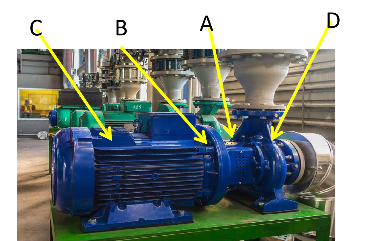
Figure 4 Monitoring Scenario: Pump and Motor
(A) Bearing Box: Bearing faults (wear, peeling, poor lubrication) account for over 40% of pump failures, resulting in high-frequency impact sounds and abnormal vibration noises.
(B) Pump Shell and Impeller Area: Capture impeller cavitation (characteristic: high-frequency explosion sounds), blade fractures or foreign object impacts.
(C) Motor: Monitor motor bearing faults, rotor breakage (characteristic: periodic electromagnetic noise), and fan blade damage.
(D) Coupling Guard: Detect misalignment (periodic friction sounds), coupling wear or loose vibration of the guard.
| 4 Machine Pump Monitoring System Configuration List | ||
| 1 | Unidirectional accelerometer | 24 |
| 2 | Three-axis accelerometer | 8 |
| 3 | Sensor cable (1.5m) | 24 |
| 4 | Sensor cable (1.5m) | 8 |
| 5 | Pre-amplification and filtering module | 4 |
| 6 | Signal Acquisition and Communication Module | 4 |
| 7 | Battery-powered module | 4 |
| 8 | Power supply and charging management module | 4 |
| 9 | Collection system casing | 4 |
VI. Customer Feedback
The customer stated that this sound vibration detection solution effectively enhanced the visualization of equipment status and the efficiency of diagnosis,
providing a reliable technical means for implementing predictive maintenance in the equipment area.