| Case Name: | Application Case of Petrochemical Concealed Leakage Point Detection |
| Industry Field: | Petrochemical / Chemical Plant Operation and Maintenance |
| Detection Object: | Process Pipelines, Valves |
| Equipment Used: | 128-channel Acoustic Imaging Instrument (Model: AC-D128LK) |
| Detection Time: | April 2025 |
| Detection Location: | A Petrochemical Co., Ltd. |
I. Application Background
(1) On-site Background
In petrochemical plants, there are numerous high-pressure, flammable, and explosive gas media
(such as compressed air, nitrogen, hydrocarbon gases, etc.).
During long-term operation, pipeline flanges, valve packing, instrument interfaces, etc.,
are prone to minor leaks due to aging seals, vibration, or temperature changes.
(2) Core Customer Requirements
① Conduct gas leakage detection without stopping the plant.
② Quickly identify and locate early, minor leakage points.
③ Daily inspection in the complex environment of the plant area.
④ Reduce reliance on manual experience and improve inspection efficiency.
II. Detection Challenges
① The pipelines in the plant area are densely located and have complex structures.
② Leakage points are often located at high altitudes, narrow spaces, or inaccessible positions.
For pipe racks and air-cooled island areas, inspectors need to set up scaffolding, which is time-consuming, labor-intensive, and poses risks of working at heights.
③ Background noise is high (pumps, compressors, fans).
④ Traditional detection methods require close contact, which poses safety risks.
III. Solution and Detection Method
Using the 128-channel acoustic imaging instrument leakage model (Model: AC-D128LK) independently developed byWisono Technology Co., Ltd., a non-contact,
visual acoustic source positioning method is adopted. The high-frequency ultrasonic signals generated by gas leakage are used for positioning.
Through acoustic imaging technology, the invisible leakage acoustic sources are visualized.
Characteristics:
① Non-contact detection to ensure personnel safety;
② No need for equipment shutdown;
③ Capable of identifying abnormal sound sources in complex noise environments;
④ Real-time imaging, quickly locating the leakage location.
IV. Description of the On-site Detection Process
① Plan the inspection route for the equipment area;
② Scan key areas such as pipeline flanges, valves, and instrument joints;
③ Observe the acoustic imaging map in real time to identify the distribution of abnormal sound sources;
④ Precisely locate the leakage point position;
V. Display of Detection Results and Effects
Detection results: Can locate concealed leakage points in strong background noise.
Leakage points: Snap fasteners, pipelines, valves
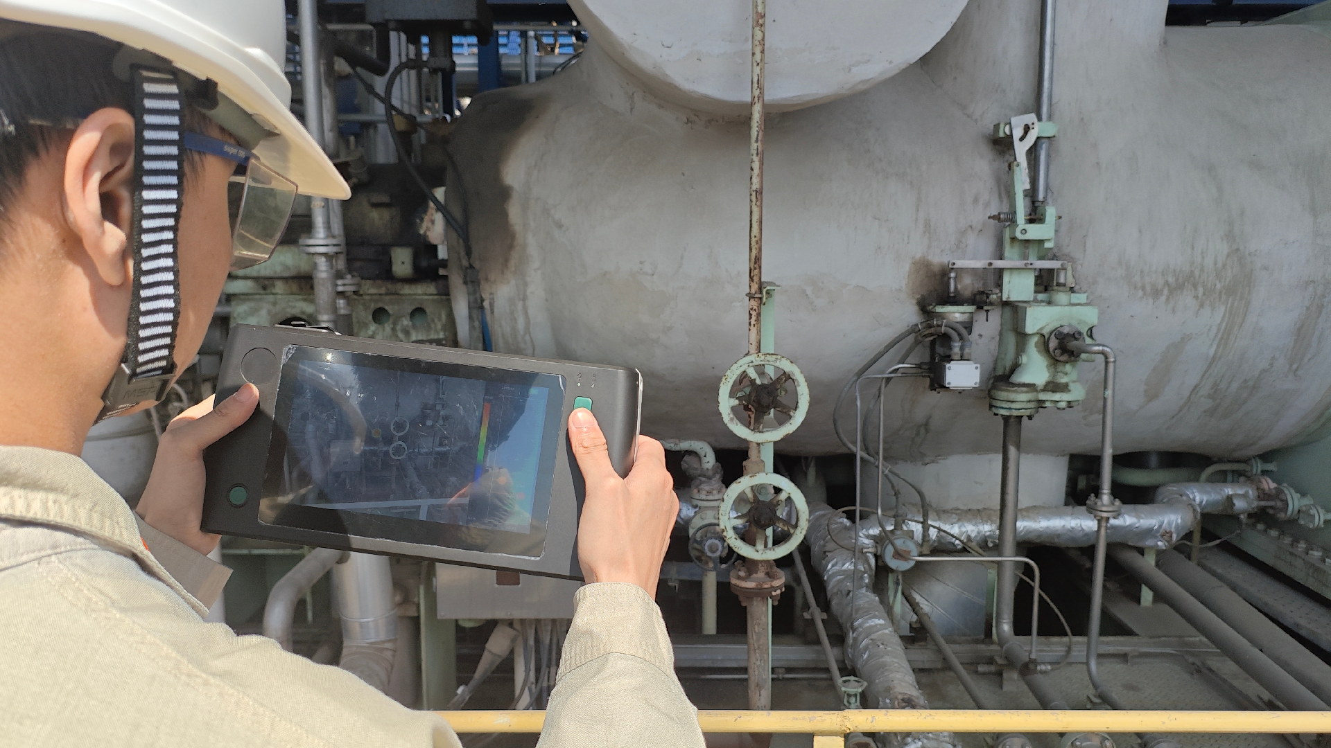
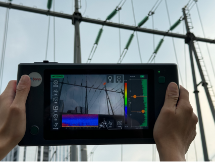
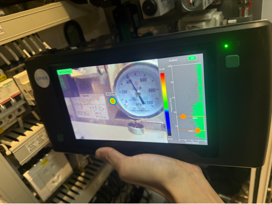
Figure 1-1 Actual Measurement of Valve Leakage
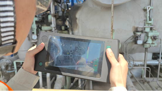
Figure 1-2 Actual measurement of valve leakage
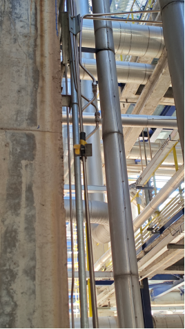
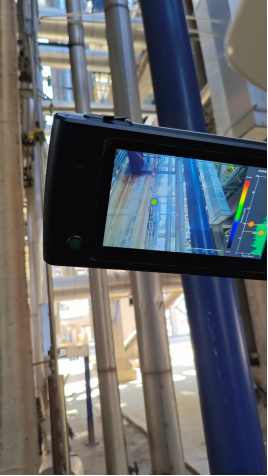
Figure 2 Actual measurement of snap ring leakage
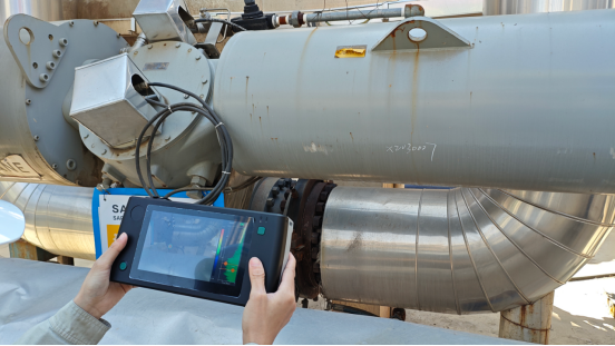
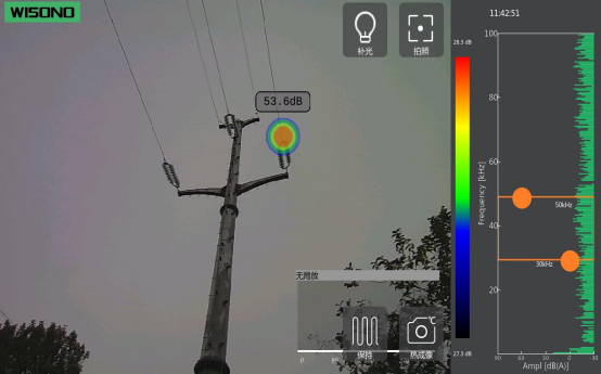
Figure 3-1 Measured Leakage of Pipeline
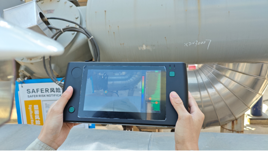
Figure 3-2 Measured Leakage of Pipeline
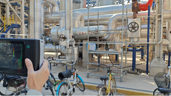
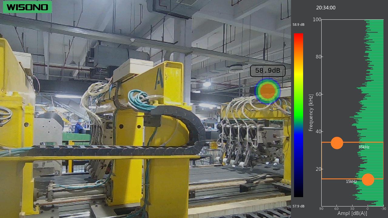
Figure 4-1 Measured Leakage of Pipeline
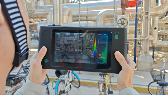
Figure 4-2 Measured Leakage of Pipelines
VI. Customer Feedback
① The customer believes that this equipment is highly suitable for routine inspection scenarios and can effectively detect hidden leaks in advance.
② They highly praise the intuitive, rapid, and non-contact detection method of acoustic imaging.
③ They clearly stated that this equipment has engineering application and promotion value.